Planning Workflow
Distro Editor
The Distro Editor is the detailed workspace for assigning equipment to outputs, adjusting quantities, recording notes and building downstream distribution.
What the Distro Editor is for
The Distro Editor is where the practical detail of a distribution unit is entered. It shows the selected distro, its source, its phase loading, output cards, Socapex circuits where applicable and the equipment library available to assign.
Use this page when you need to place real equipment onto outputs, change quantities, add notes, feed child distros or understand exactly how an individual distro is being loaded.
Selecting the distro to edit
The active distro can be changed from the Editing Distro selector at the top of the editor. Opening a distro from System Overview, Power Sources or Distro Overview also sets it as the active distro automatically.
This allows fast movement between overview pages and detailed output editing without losing the current project context.
When reviewing the system, use Open on a source or distro card to jump directly to the relevant distro in the editor.
Equipment library
The equipment library appears on the left of the editor. It contains company equipment loaded from the workspace library plus any custom equipment created for the current project.
Use search and category filtering to find items quickly. Equipment can be dragged onto an output, or added using the dropdown within an output card.
- Company equipment is maintained at workspace level.
- Custom equipment is stored inside the current project.
- Equipment entries include name, category and wattage.
- Assigned item quantities multiply the wattage automatically.
Assigning and moving equipment
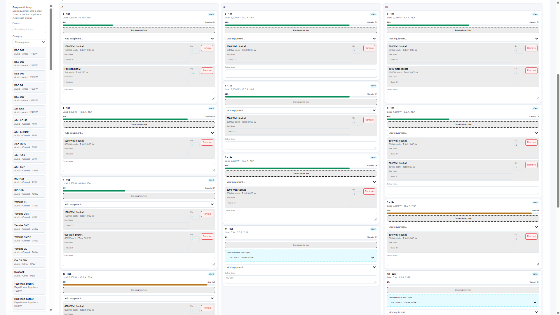
Drag equipment from the library onto an output drop zone to assign it. Once assigned, the item appears on that output with a quantity, wattage and notes field.
Assigned equipment can also be dragged between compatible output areas within the same distro. This is useful during balancing because you can move loads between phases and immediately see the recalculated result.
- Search for the equipment item.
- Drag the item onto the required output or circuit.
- Adjust quantity if more than one item is connected.
- Add item notes if required for patching, location or operating restrictions.
- Review output, distro and source loading after the change.
Item notes and output notes are valuable in reports. Use them for cable routes, stand numbers, departments, dimmer references, rig positions and supplier notes.
Output cards
Each output card displays the output name, phase, connector type, rating and current loading. Where it feeds a downstream distro, the card includes that downstream draw and identifies the linked distro. Parent distro totals and phase draws include every linked downstream level.
For three-phase outputs, the load is distributed across L1, L2 and L3. For single-phase outputs, the load is applied to the assigned phase. Socapex circuits are displayed as individual circuit outputs grouped by phase.
If an output approaches capacity or becomes overloaded, the warning system updates immediately. Resolve critical output warnings before issuing reports.
Source and phase cap
The selected source is shown near the top of the editor. Where a larger distro is fed from a lower-rated compatible high-current three-phase source, the editor may show a phase cap. This means the distro input exists at one rating but is limited by the upstream source rating.
The phase cap is important because it prevents the planner from treating a large distro as if its full input rating is available when the upstream source is smaller.
If a 400A distro is fed from a 200A source, the planner must evaluate loading against the 200A source limit rather than the physical distro maximum.
Downstream distro feeds
Eligible outputs show a downstream distro selector even when no compatible unassigned distro is currently available. Eligible ratings are 32A and 63A single phase, and 16A through 400A three phase. Selecting a child distro connects it to the Auto Source created from that output.
The planner prevents circular feed loops and filters incompatible connector types so the hierarchy remains electrically sensible. Loads on the downstream distro are included in the parent output and upstream source calculations.
- Only eligible outputs create Auto Sources.
- Socapex outputs do not create Auto Sources.
- A child distro can only be assigned to one source at a time.
- The parent output includes downstream load in its calculation.
- Open downstream distro changes the editor directly to the linked child.
Use downstream distro feeds to represent systems such as generator → main distro → area distro → local breakout.
Parent and sticky phase draws
When the current distro is downstream, a collapsible Parent distro phase draw card appears below the distro selector. It shows the parent L1, L2 and L3 current, rating, percentage and capacity bars, and identifies the feeding parent output.
Use Open parent distro to move directly upstream. The current distro phase-draw strip remains pinned while scrolling through long output schedules so phase balance stays visible while equipment is moved or added.
Socapex outputs
Socapex outputs are expanded into their individual circuits by phase. This makes it possible to place loads on the actual circuit numbers rather than treating the Socapex as a single combined output.
Where paired Socapex outputs share breaker capacity, the editor shows linked capacity information. Review these shared loads carefully because two physical sockets may be protected by one breaker.
A Socapex circuit can appear acceptable in isolation while the shared breaker pair is overloaded. Resolve shared breaker critical warnings before issuing documentation.
Related articles
Send feedback or request extra documentation for this topic.